STB100 Beacon Test Bench
Test all Cospas-Sarsat ELTs, EPIRBs, PLBs, and AIS Transceivers

STB100 BEACON TEST BENCH
General Overview
The STB100 Beacon Test Bench is becoming known as The Standard in beacon testing equipment worldwide. No other test equipment provides this level of detailed, accurate, and reliable measurements for both Cospas-Sarsat approved emergency beacons and AIS Transceivers (new).
The STB100 Beacon Test Bench is the perfect tester for shore-based maintenance facilities, avionics test facilities, beacon manufacturers, beacon developers, and IMO radio surveyors.
STB100 Beacon Test Bench
The STB100 measures all 406 MHz, 121.5 MHz, and 243 MHz emergency beacons, including AIS EPIRBs (new), 406 MHz frequency stability, and AIS Transceivers (new).
The STB100 also has very accurate DC current and voltage measuring allowing for characterization of power supplied to a beacon, as well as measuring leakage current down to 200nA.
The user friendly STB100 software is included free with the purchase of your STB100 unit and can be downloaded directly from our website. Alternately, advanced users can use the optional API command set to customize their own User Interface.
Features Included
- measures all 406, 121.5, 243, and AIS-EPIRB parameters
- measures AIS Transceivers (Class A & B)
- receives all Cospas-Sarsat frequency channels and decodes all protocols
- measures and computes 406 MHz frequency stability
- uses direct 50Ω RF input at full power – no attenuator needed
- has optional Antenna input
- monitors the DC supply to a beacon over a wide range: 1 to 30V, 5mA to 8A
- measures Vin to Vout low dropout voltage of 50mV/A
- measures beacon leakage current
- has overload protection
- has internal GPS engine for measuring delta distance
- streams measurement data into delimited text files – for easy analysis
- creates custom Beacon Test Report PDF
- creates custom IMO Test Report PDF
- connects up to two external temperature probes
- customizable user interface with API command set
- Cospas Sarsat Second Generation Beacon ready (coming soon)
Included with your Test Bench purchase
- STB100 Beacon Test Bench
- AC Power cord
- USB to PC cable
- Active GPS antenna
- RF input antenna
- Operator’s Manual
- Certificate of Conformance
- Certificate of Calibration
- free software and firmware updates online
- outstanding customer support
DOWNLOADS:
Software Revision 5.10 Notes – Apr 17, 2025:
- New Real-Time Passed/Failed counter (Limit Tester)
- Limit Tester file reference added to Test Report
- Addition of ICAO Operator Designator
- EVM compliance with new C/S specification (SGB)
- Regional Settings improvements
- Minor bug fixes
Software Revision 5.00 Notes – Oct 21, 2024:
- Full SGB measurement capabilities, including:
· Short Term Stability
· Full 63 Hex ID (previously
75 Hex ID)
- New, improved PDF Test Report layout
- Updated Limit Tester fields
- Medium Term Slope fix (FGB)
- Regional settings fixes
Software Revision 4.20 Notes – Dec 20, 2023:
- Test Report generator bug fix
- Minor bug fixes
Software Revision 4.10 Notes – Nov 10, 2023:
- Minor bug fixes
Software Revision 4.01 Notes – Apr 25, 2023:
- Second Generation Beacon measurement capability
- User comments field on Test Reports
- Improved RLS decode
- Improved Frequency Stability
- Minor bug fixes
Software Revision 3.30 Notes:
- Improved Limit Tester functions
- 121/243 Training Frequency updates
Software Revision 3.21 Notes:
- 121.5 MHz antenna performance modifications
Software Revision 3.20 Notes:
- Improved IMO Auto Test
- Modulation Index measurement improvements
- Minor bug fixes
Software Revision 3.10 Notes:
- Added capability to test AIS Transceivers (Class A and Class B)
- Added capability to test AIS-EPIRBs
- Introduced the Oscillograph
- Added ELT (DT) Protocol decoding
- Added Protocol as a Limit Test parameter
- Added custom Test Report logo
- Added Get GPS location function
- Implemented Improvements to determining long vs short bursts
- Corrected upper/lower limits for Phase Symmetry in Limit Setup
- Added Custom filename numbering
- Implemented Minor bug fixes
Measurements Screenshots


Setup Screenshots

Limits Screenshots

IMO Test Screenshots


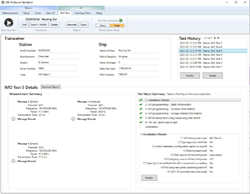

Individual Tests Screenshot

Customizable Test Report Screenshots

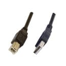
130-029 – Cable USB B Male to USB A Male – 6.5′
USB to PC Cable for the STB100 Beacon Test Bench.
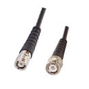
130-030 – Custom RF Cable BNC-m to TPS-m – 3′
RF Cable used to connect directly to a beacon with a TPS output port.
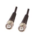

130-032 – Custom RF Cable BNC-m to TNC-m – 3′
RF Cable used to connect directly to a beacon with a TNC output port.

130-033 – Custom Length RF Cable BNC-m to BNC-m
RF Extension Cable – Choose your desired cable length. WST provides Cable Loss input factors for any cable length.

130-035 – Pilot Plug to USB Cable – 3′
Pilot Plug to USB Cable for AIS Transceivers.
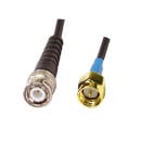
130-036 – Custom RF Cable BNC-m to SMA-m – 3′
RF Cable used to connect directly to a beacon or coax cable.
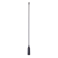
420-101 – Receiver Antenna
Beacon Tester receiver antenna.
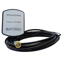
100-GAA-SMA-M – Active GPS Antenna
Magnetic mount active GPS antenna.

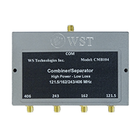
850-CMB104 – 4-Channel Signal Combiner
121/243/406/AIS signal combiner.
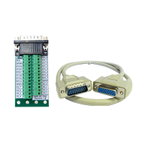

850-PRB100 – Temperature Probes
RTD Stainless Steel temperature probe attachment.
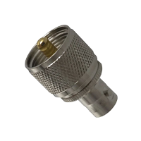
385-UHF-101 – UHF-m to BNC-f Adapter
Adapter for directly connecting an AIS Transceiver via BNC to the STB100.

850-104 – STB100 Custom Waterproof Hard Case
Waterproof (IP67 rated), dustproof, and shockproof hard case with custom foam insert for safely transporting and storing your STB100 Beacon Test Bench and accessories.
My STB100 won’t receive either 406 MHz or 121.5 MHz.
Ensure that the proper Input mode is selected. If you are receiving a beacon self-test transmission through its antenna, then select Antenna. If you are connected directly to the beacon then select Direct Connection.
When I activate the beacon in self test mode, the measurements produce questionable results. Is there a problem with the beacon?
In order to meet all of the Cospas Sarsat requirements, a beacon is allowed a 15 minute warm-up period. When testing a beacon in self test, there is no warm-up period, hence some measurements may be somewhat skewed.
Also, in self-test, the 121.5 homing transmission may be different depending on the particular beacon. Some beacons transmit a short modulated signal, some beacons transmit a shorter unmodulated signal, and some beacons transmit
no signal.
I am testing an ELT with separate 121.5 and 406 output connectors. What do I do to get the results printed on one Test Report?
The WST accessory 850-CMB102 is a low loss, 121.5/406 signal combiner. It can be used to combine the separate outputs from the ELT. Alternatively, you can complete the measurement in two steps: first, connect to the 121.5 transmitter, then start the test. Once the STB100 gives the indication that the 121.5 signal has been received, then switch the cable to the 406 transmitter without stopping the test. Once the 406 burst is received on the STB100, the measurement will be complete.
The beacon I want to measure has offset training frequencies on 121.5 and 243 MHz. How do I setup the Beacon Tester to receive these training frequencies?
Measuring Training Frequencies is easy. Go to the Setup > VHF Training Frequencies and select the training frequencies you are using.


